Signal Levels / Derating
Signal Levels in Coaxial Distribution Networks are expressed in dBµV. Such as: Output Level = 105 dBµV.
All active components that handle TV signals are specified to have a Maximum Output Signal Level.
By standard definition, this is the Output Signal Level where the unit has an Output C/N (Carrier to Noise) Level of 60dB
(When doing the specification it is actually measured using 3 carriers for controlling Intermodulation, also called an 'IMD3@60dB specification').
Example: If an amplifier has a Maximum Gain of 30dB, and a Maximum Output Signal Level rating of 105 dBµV,
the maximum Level you can put into its input, is (Maximum Output Signal Level - Maximum Gain) = 75dBµV.
If you attempt to squeeze more signal Level out of the same amplifier, for example by feeding it an Input Signal Level of 80dBµV,
and still use Maximum Gain Setting, this will work and the resulting Output Signal Level will be: (Input Signal Level + Maximum Gain)=
80+30 = 110dBµV. We say the Amplifier is now OVERLOADED.
We learned above that to keep the Industry standard of a C/N better than or equal to 60dB, the amplifier must NOT deliver more than an Output Signal Level of 105dBµV. So we now know, that the Amplifier performs a little less optimum, and now has a lower C/N than 60dB.
How much lower the C/N has become cannot directly be calculated.
Depending upon the severity of the overload, the quality of your signal deterioates, and you may begin to see artifacts (macro blocking) and noise in your TV signal. You may even end up with a black screen due to overloading. Problem is, that when you have ruined the C/N of you signal there is absolutely NOTHING you can do to make it better again after that point in your installation. It is all downhill from there !
Also note that when cascading amplifiers the C/N also becomes lower, simply due to the cascading itself (because every Amplifier also adds its own Noise to the output).
So the first rule of any installation is: NEVER run an amplifier with a higher Output Signal Level than the specified Maximum !
However, it does not stop there! This next information may prove to be even more important and severe than the above Output Level issue.
If you read the above information again, you will notice that the Maximum Output Signal Level specification was done measuring the C/N Level using 3 x TV carriers (channels) in the setup.
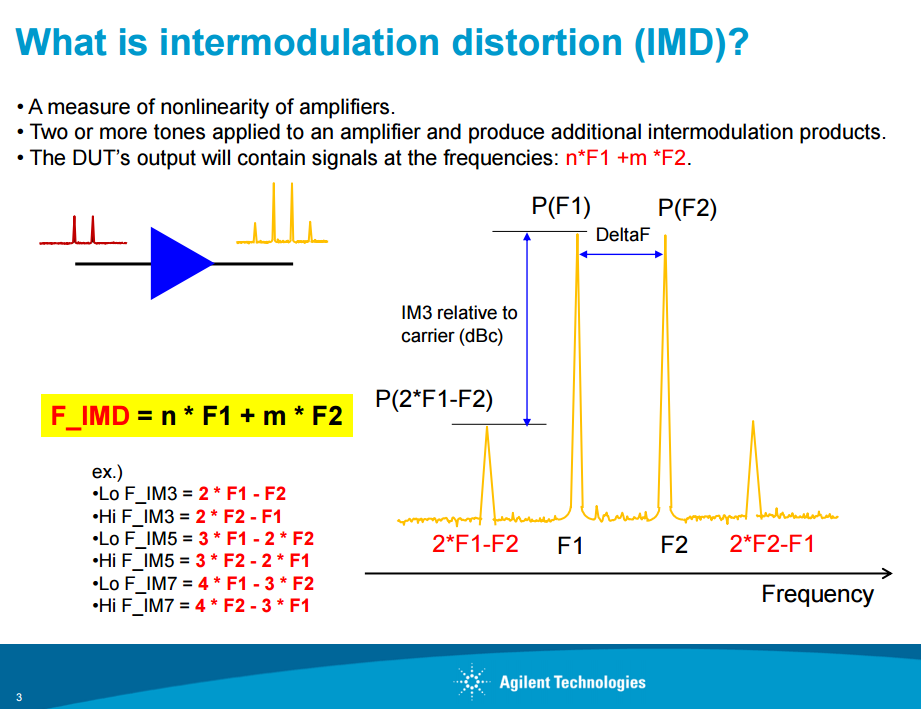
What is important to know is, that for every extra channel you put into the Amplifier in excess of the 3 channels that was used for Specification Measurement, the Maximum Output Signal Level for a C/N at, or better than 60dB goes down due to more Intermodulation Noise.
In plain text, this means:
The more channels you put through an Amplifier, the lower Signal Level you can get out of it if you want to keep your quality
In todays reception of TERrestrial signals, it is not uncommon to have between 6 to 12 channels (also called multiplexes or carriers) received by any one antenna. All carriers will be picked up by the antenna, and they will be seen by the Amplifiers, even if the User does not care to watch the channels. For cable TV the number of channels can be even higher, and here the number of channels can be as high as 45-65 channels !
So, now you need a method to calculate how much less signal you can get out of the Amplifier than the specified Maximum Output Signal Level, when you have many more channels than 3.
The solution is what we call derating.
Using a formular, and the known number of carríers, we must derate the original Maximum Output Signal Level Specification, to get a dB Level you have to deduct from the Maximum Specification of the Amplifier. Due to the differences in their modulation form, the formular is different for SAT reception and MATV/CATV reception. Furthermore, the minimum C/N for the specification measurement for SAT is 35dB:
- Satellite signals, derating factor = 10 x log(Number of channels -1)
- Terrestrial and cable signals, derating factor = 7.5 x log(Number of channels -1)
The 'Number of channels' here are the REAL total number of channels MINUS 3.
So, for a Terrestrial reception, receiving 10 multiplexes, the calculation becomes: 7.5 x log((10-3) -1) = 5,84 dB,
and for a satellite reception, receiving an average of 32 Transponders (a full polarity) the calculation becomes: 10 x log((32-3) -1) = 14,47 dB
The results are the dB you must deduct from the Amplifiers specification of Maximum Output Signal Level (in example 105dBµV) to calculate the REAL Maximum of the Amplifier.
For a Satellite Signal the Maximum Output Signal Levels will then be: 105dBµV - 14,47 dB = 90,53 dBµV, and for a Terrestrial Signal the Maximum Output Signal Levels will then be: 105dBµV - 5,84 dB = 99,16 dBµV
The above figure (105dBµV) are just for the sake of argument and an example.
For a real Multi switch product the Maximum Output Signal Level specification are typically 100dBµV for SAT and 88 dBµV for TER.
Using the same number of channels or transponder as in the above examples, the calculations becomes:
- SAT: 100dBµV - 14,47 dB = 85,53 dBµV, and
- TER: 88dBµV - 5,84 dB = 82,126 dBµV
You will notice, that the two signal paths of SAT and TER seems to be specified very different in the Datasheet, but when you do the math using real life numbers for number of carriers, the SAT and TER Amplifiers' performances are actually pretty much the same.
If you do not take this matter into consideration, it should be obvious that in cases where you drive the Maximum Ouitput Signal Levels specification you get from the datasheet through your installation, you will deterioate the quality of your signal, and get a result that may seem very strange and frustrating, especially because it seems that you have just followed the specification.
Well you have NOT !. Because You must ALWAYS consider derating.
NOTE: CATV Distribution Amplifiers are normally developed to work with many more channels from the start, and are typically specified a little different. Often you will see something like this for the Maximum Output Signal Level Secification in the Datasheet:
105dBµV CTO/CTB@CENELEC42.
For a product like this, you only need to do any derating if the number of carriers are higher than 42. So instead of 3, you need to insert 42 into the formulars above.
REMARK: The two formulars introduced in this article, are using heuristic values. It means, they cannot be proven to be 100% correct using math. But may years of trials and error has proven that this way of finding the best working derating values, are created via these formulars.
For the same reason, and also because Satellite signals, Terrestrial and CableTV Signals have different Modulation Forms that also differs in the amount of Error Corrections built-in, you may see installations where the missing of derating attention causes all kinds of trouble, and again, in other installations you'll get away with ignoring it, and still have a good quality TV signal.
Common Sense and many Years of Installation experiance will most probably tell you in the end, that adhering to the rules and theory of derting is a habit well justified.