Create a New Plan
When You click the 'Create' Button on the 'Planner Home Page', you are shown this 'Plan Details Page' you see below:
It has blank Form Fields for you to fill out with all needed Plan Information and Details.
Once a Plan is described via this form, you may start doing the actual Network System Design.
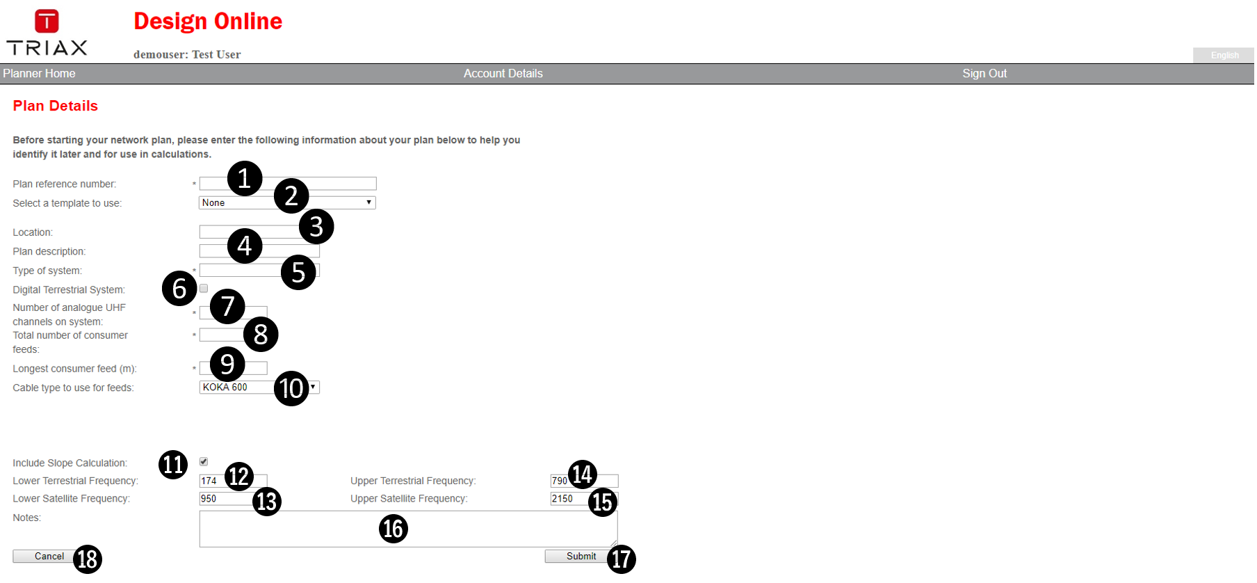
This Page has 13 fields you need to fill out, two dropdown list boxes to select from and a few buttons to click. Each element is carefully described in the table below.
It is very tempting to only briefly fill out the fields because you are anxious to get the actual design started, and in most cases you will get away with filling out most of the fields with very little information or even garbage.
HOWEVER: we advise you to carefully fill out all fields with correct information, as it will make your future DOL design life a lot easier as you work more with it.
| Number | Field/Element Name | Description of Field/Element | Figure (if any) |
|---|---|---|---|
| 1 | Plan reference number: | This is the most important text field of any new Plan. Two plans CANNOT share the same text here, so you should use a logical way of naming or numbering your plans, so it is easy for you to find them in the future. You may need to combine the identifying informations you need into more of the following fields, so you do not end up with a very long text here. | |
| 2 | Select a Template to use: | In this dropdown list, a number of different types of plans are found. They will be different from country to country, due to the TRIAX Product Portfolio available in your country. If you just leave this field at the default 'None' selection, you will start with a totally blank design, and can add anything from there. If you select one of the Templates, a portion of the Design Plan is already done for you, and you may add or even delete to the Plan later. Currently only Multiswitch type of Templates are available. (Checkout this discussion of Templates versus Plan Copies) | Figure 2, Templates dropdown |
| 3 | Location: | Here you should write the postal address or other geographical reference to identify where the installation this Plan describes is to take place. | |
| 4 | Plan Description | This field allows you to give more information to describe the installation. | |
| 5 | Type of System: | Recommended texts are: MATV, CATV or CATV, but it is totally up to you. | |
| 6 | Digital Terrestrial System | TRIAX DOL was first created and introduced at a time where installations used analogue reception. Today almost ALL installations receive Digital receptions, so you should click and checkmark this field. NOTE: We are talking INPUTs here, NOT outputs. |
|
| 7 | Number of analogue UHF channels on system | If you clicked and checkmarked the field 6 above, you should understand 'digital' instead of 'analogue' here. This is the combined total of all carriers available on all of the inputs you will define in your plan. If, for example, you will have 4 carriers available from a VHF aerial, and 8 carriers avialable from a UHF aerial, you should type 12 here. If your Signal Source instead is a Headend with for example 38 carriers/channels, you should write 38 here. This number will allow TRIAX DOL to correctly re-calculate (derate) the Maximum Output Specification of all selected active products so you do not accidentally overload them. The number of carriers shall also be adjusted at every Signal Source input in your plan and will override any info in this field. (See more detail about derating here). | |
| 8 | Total number of consumer feeds | This field is to allow you to show howmany outlets the full Plan will have in the Plan List on the 'Planner Home Page'. If, for example, you are designing an SMATV multiswitch system, using only one TMS 512 SE multi switch, you would write 12 here. For two similar, but cascade switches, like the TMS 512 CE, write 24 here. For a CATV system you may have a much higher number to write here. This number is to allow you to quickly find a similar Plan when you need to do a new Plan. This way you can start with a copy of an old plan, and continue from there. This will save you from a lot of work, while still keeping your original older Plans along with the new Plan. | |
| 9 | Longest consumer feed (m) | This number is mainly important in multiswitch installations. Here you should write the single and absolutely LONGEST cabledrop from any multiswitch in the system Plan, and to its outlet (in meters). This allows DOL to make a check at every multi switch output, and it will even show you the Signal Output Level directly at the multi switch AND the Signal Level after having passed through this number of meters of coax cable. It will use the specification of the coax cable type selected below in field 10 to calculate the correct cable loss and any cables slopes. Using this to your best advantage, it will actually let you use less time making simpler looking design plans. This is because DOL will always give you the worst case result at any multiswitch output (longest cable drop), so you do NOT need to add every single cable and outlet to your plan, if you don't need to have them there (other than to show an exact picture of everytyhing, and get everything into the BOM of course). |
|
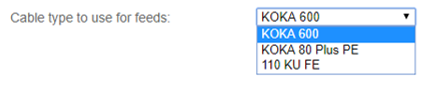
| 10 | Cable type to use for feeds. | This dropdown presents a number of cable types known to the system, sold in your country. This is to allow DOL to do the cable loss calculation mentioned above in field 9. NOTE: In the actual Plan you can use ANY of the cable types that are available to you for selection, if you need to and DOL will use their cable specifications whenever needed. This field is ONLY for DOLs safety calculation of long cabledrops from multi switches, so you are advised to pick the cable type you normally use for Multi switch consumer drops here. |
Figure 3: Cable type dropdown list |
| 11 | Include Slope calculation | Until recently DOL did its cable loss calculations based upon what was seen as 'worst case' Signal Level values. This meant that Signal Levels were shown at their highest frequency Levels, because that is where the losses are highest in a coaxial cable. Now DOL can correctly, and on-the-fly, calculate the frequency dependent losses (most prominent at coaxial cables) and will show you the Signal Level values both at the lowest frequency and at the highest frequency of an input or an output. This also means that any Signal Level graph shown by DOL will clearly show this difference of levels at low and high frequency ends. You are highly advised to select (checkmark) this feature to get a Signal Level indication as accurate and realistic as possible. | |
| 12 | Lower Terrestrial Frequency | This field was originally meant to hold the lowest Terrerstrial frequency used on any multiswitch input of the system. Today TRIAX DOL can handle both MATV, SMATV and CATV systems that uses a more versatile range of input signals. Frequency ranges are mainly handled automatically dependant upon the specifications of the product inputs used in the plan. It is good karma to type the lowest frequency used here anyway (Examples: 5, 47, 88, 174 or 470 (MHz). | |
| 13 | Lower Sattelite Frequency | This field should normally read: 950 being the lowest satellite SAT-IF frequency normally used in any satellite distribution system. | |
| 14 | Upper Terrestrial Frequency | This field was originally meant to hold the highest Terrerstrial frequency used on any multiswitch input of the system. Today TRIAX DOL can handle both MATV, SMATV and CATV systems that uses a more versatile range of input signals. Frequency ranges are mainly handled automatically dependant upon the specifications of the product inputs used in the plan. It is good karma to type the highest frequency used here anyway though (Examples: 694, 790, 862 (MHz). | |
| 15 | Upper Satelite Frequency | This field should normally read: 2150 being the highest satellite SAT-IF frequency normally used in any satellite distribution system. BEWARE: that many multiswitch products are (correctly) specified to handle higher SAT-IF frequencies than 2150 MHz. For the sake of calculations, and because NO satellite SAT-IF goes higher than 2150 MHz in real life, this is what DOL uses, and you should NOT type anything else but 2150 here. | |
| 16 | Notes: | This is a fully free text field that allows you to record any additional information you would like to store for this plan or installation. | |
| 17 | Submit | This is the SAVE button. Before you click any other button or link to get away from this page, DO NOT FORGET TO CLICK THIS BUTTON FIRST!. This will store all your inputs for this plan to the DOL databse, and you are ready to start doing the actual plan design. If you fail to click this button, your input is not stored, and may be lost. DOL will attempt to give you a warning first, but this can be dependant upon browser settings and may not always save you from disaster! NOTE: the 20 minute Web Server timeout period also applies here. This means that you should NEVER spend more than 20 minutes on this page before you hit this 'Submit' button or you will loose any un-saved and un-submitted information. When you click 'Submit' your plan details are stored, and the system will bring you to an updated version of the 'Plan Details Page' with more buttons and features (Click here to go to a description) |
|
| 18 | Cancel | WARNING: This button tells DOL that you have changed your mind, and does not want to create this plan. DOL will attempt to give you a warning first, but this can be dependant upon browser settings and may not always save you from disaster! Hitting this button deletes the un-saved Plan of this Page and returns you to the 'Planner Home Page' so be careful not to hit it accidentally ! |