Understand Specifications
This page will briefly discuss the most important specification types and their meaning that are used for all TRIAX products.
Important Specification definitions:
- Absolute versus Relative figures
- Signal Level (dBµV)
- Maximum Output Signal Level
- Bandwidth (MHz)
- Noise (dB)
- Noise Figure (dB)
- Signal/Noise - S/N - ratio (dB)
- Carrier/Noise - C/N - ratio (dB)
- Gain (dB)
- Attenuation (dB)
- Return loss (negative dB)
- Through Loss/Insertion loss (dB)
- Crosstalk/Isolation (dB)
Legend:
- Arrow up indicate that the higher the number is the better this specification is.
- Arrow down indicate that the lower the number is the better this specification is.
What is...?
Absolute versus Relative figures.
Using absolute figures when dealing with TV Signals is not practical as it may result in measurement figures (numbers) that are both very small and very high. Furthermore it involves multiplications when dealing with amplification, and divisions when dealing with losses. This makes handling measurements using absolute figures very complex and difficult.
- Relative figures are normally used instead
- (dB - decibel) is a logarithmic unit. The reference is = 1µV
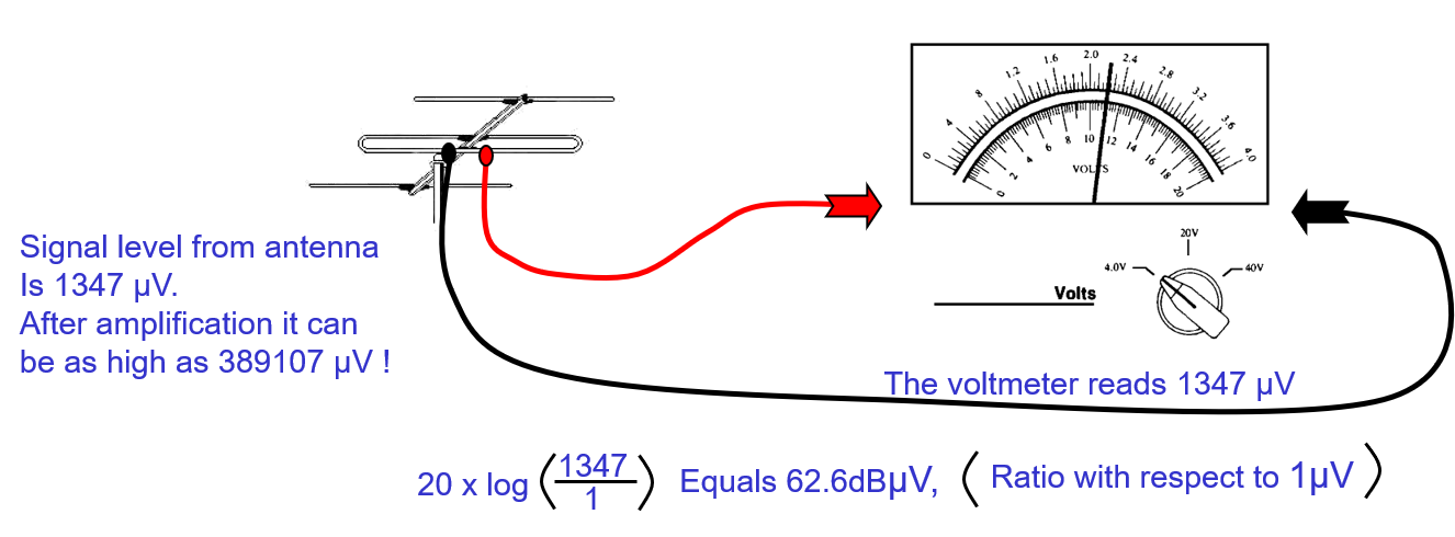 In above example the antenna provides a Signal Output, that, when measured absolute is 1347 µV
If you need to amplify this signal level, it may end up with an absolute Signal Level of 16164 µV, and in a larger distribution system as high as an absolute level of 389107 µV !
In below tables it is easy to see how an absolute figure (µ Volt) compares to its Logaritmic version (dBµV) and how the Logarithmic figures are much smaller.
 |
 |
dB is a Ratio beytween a measured value and an absolute reference value (1µV)
60 dB means a 1000:1 ratio.
 Using a Logarithmic scale both very small and very large numbers fit well into the same space and become much more manageble. Furthermore, amplification and Attenuation becomes much easier when you need to do calculatioons, because now it is simply a matter of addition and subtraction respectively.
Using the first example with an antenna providing an absolute Output Signal Level of 1347 µV.
This is equivalent to 62,6dBµV. Amplifying it with a 20dB amplifier results in an Output Signal Level of the Amplifier of (62,6 + 20) = 82,6 dBµV
A Signal ?
In electronics, a signal is an electric current or electromagnetic field used to convey data from one place to another. The simplest form of signal is a direct current (DC) that is switched on and off; this is the principle by which the early telegraph worked (first Morse code sent in 1844).
- More complex signals consist of an alternating-current (AC) or electromagnetic carrier that contains one or more data streams.
- Data is superimposed on a carrier current or wave by means of a process called modulation.
- Signal modulation can be done in either of two main ways: analogue and digital. In recent years, digital modulation has been getting more common, while analogue modulation methods have been used less and less. There are still plenty of analogue signals around, however, and they will probably never become totally extinct.
- Except for DC signals such as telegraph, all signal carriers have a definable frequency or frequencies. Signals also have a property called wavelength, which is inversely proportional to the frequency.
- In some information technology contexts, a signal is simply "that which is sent or received“, thus including both the carrier (see above) and the data together.
Signal Level
In coaxial TV Distribution, Signal Levels are expressed in the unit dBµV. The higher the Signal Level the longer it will travel over a cable before it has lost too much energy to be usefull. American specifications often use the unit dBm, which is directly correlated to dBµV via this formular: Value in dBm + 108.75dB = Value in dBuV.
Maximum Output Signal Level
The Maximum allowed Output Level an active component (such as a Distribution Amplifier) should be adjusted to provide while keeping its C/N at or below 60dB.
This specified Output Signal Level was measured using 3 carriers, and are expressed in dBµV. If your TV Distribution Signal carries more than 3 carriers, you must 'derate' the specification, so you set the amplifiers maximum Output Level LOWER than the maximum specified, or you risk creating Intermodulation Distortion. Read more here.
Bandwidth
Bandwidth has a general meaning of how much information can be carried in a given time period (usually a second) over a wired or wireless communications link.
- For example, a link with a broad bandwidth - that is, a broadband link - is one that may be able to carry enough information to sustain the succession of images in a video presentation. More technically, bandwidth is the width of the range of frequencies that an electronic signal occupies on a given transmission medium. Any digital or analogue signal has a bandwidth.
- In analogue systems, bandwidth is expressed in terms of the difference between the highest-frequency signal component and the lowest-frequency signal component.
- Frequency is measured in the number of cycles of change per second, or hertz.
- A typical voice signal has a bandwidth of approximately three kilohertz (3 kHz); a television (TV) broadcast video signal has a bandwidth of six to eight megahertz (6-8 MHz) -- some 2,000 times as wide as the voice signal.
Noise
Noise is unwanted electrical or electromagnetic energy that degrades the quality of signals and data. Noise occurs in digital and analogue systems, and can affect communications of all types, including text, programs, images, audio, and telemetry.
In a hard-wired circuit external noise is picked up from appliances in the vicinity, from electrical transformers, from the atmosphere, and even from outer space.
Normally this noise is of little or no consequence. However, during severe thunderstorms, or in locations were many electrical appliances are in use, external noise can affect communications.
In general, noise originating from outside the system is inversely proportional to the frequency, and directly proportional to the wavelength. At a low frequency such as 300 kHz, atmospheric and electrical noise are much more severe than at a high frequency like 300 megahertz.
Noise generated inside wireless receivers, known as internal noise, is less dependent on frequency. Engineers are more concerned about internal noise at high frequencies than at low frequencies, because the less external noise there is, the more significant the internal noise becomes Communications engineers are constantly striving to develop better ways to deal with noise. The traditional method has been to minimize the signal bandwidth to the greatest possible extent. The less spectrum space a signal occupies, the less noise is passed through the receiving circuitry. However, reducing the bandwidth limits the maximum speed of the data that can be delivered
Noise Figure
A method for quantifying the electrical noise generated by an active device.
- The noise figure is the ratio of the noise power at the output of a device to the noise power at the input to the device, where the input noise temperature is equal to the reference temperature (290 °K).
- The noise figure is usually expressed in decibels.
- The noise figure should be as low as possible.
Gain
The amplification factor, also called gain, is the extent to which an amplifier boosts the strength of a signal.
Amplification factors are usually expressed in terms of power.
- The decibel (dB), a logarithmic unit, is the most common way of quantifying the gain of an amplifier.
- For power, doubling the signal strength (an output-to-input power ratio of 2:1) translates into a gain of 3 dB; a tenfold increase in power (output-to-input ratio of 10:1) equals a gain of 10 dB; a hundredfold increase in power (output-to-input ratio of 100:1) represents 20 dB gain.
- If the output power is less than the input power, the amplification factor in decibels is negative. If the output-to-input signal power ratio is 1:1, then the amplification factor is 0 dB.
Attenuation
Attenuation: The decrease in intensity of a signal, beam, or wave as a result of absorption of energy and of scattering out of the path to the detector
- Attenuation is usually expressed in dB.
- "Attenuation" is often used as a misnomer for "attenuation coefficient“, which is expressed in dB per kilometre.
- A distinction must be made as to whether the attenuation is that of signal power or signal electric field strength
Return Loss
The ratio, at the junction of a transmission line and a terminating impedance or other discontinuity, of the amplitude of the reflected wave to the amplitude of the incident wave
- Return loss is usually expressed as a negative figure in dB, however, often the negative sign is forgotten and the value is shown as a positive value.
- Return loss should be as high as possible. (-15dB is better than –10 dB)
- Return Loss is a measure of the ratio of signal power transmitted into a system to the power reflected (i.e. 'returned'). In simple terms, it can be thought of as an echo that is reflected back by impedance changes in the link. Any variation in impedance from the source results in some returned signal. Real-life cabling systems do not have perfect 75 Ohm impedance structure and matching, and therefore have a measurable return loss
- In addition, not all connecting hardware components in a link may have 100% equal 75 Ohms impedance. At every connection point there is the potential for a change in impedance. Each change in the impedance of the link causes part of the signal to be reflected back to the source.
- Return loss is a measure of all the reflected energy caused by variations in impedance of a link relative to a source impedance.
- Each impedance change contributes to signal loss (attenuation) and directly causes return loss
Signal to Noise Ratio - S/N
A measure of the quality of an electrical signal, usually at the receiver output.
- It is the ratio of the signal level to the noise level, measured within a specified bandwidth (typically the bandwidth of the signal).
- It is usually expressed in decibel. The higher the ratio, the better quality of the signal.
Carrier to Noise Ratio C/N
A measure of the quality of a modulated carrier at the receiver input
- It is the ratio of the power of the carrier to the power of the noise introduced in the transmission medium, measured within a specified bandwidth (usually the modulated carrier's bandwidth)
- It is usually expressed in decibel
- The higher the ratio, the better quality of the received carrier
Through Loss / Insertion Loss
The loss resulting from the insertion of a device in a transmission line
- Expressed as the reciprocal of the ratio of the signal power delivered to that part of the line following the device to the signal power delivered to that same part before insertion.
- Insertion loss is usually expressed in dB.
Isolation / Crosstalk
Isolation: The inverse of crosstalk.
- A measure for how much the undesired signal is attenuated on one transmission line compared to the amplitude of the undesired signal in its intended transmission line
- Isolation is expressed in dB and should be as high as possible
Crosstalk (XT):
- Undesired capacitive, inductive, or conductive coupling from one circuit, part of a circuit, or channel, to another
- Any phenomenon by which a signal transmitted on one circuit or channel of a transmission system creates an undesired effect in another circuit or channel
- Normally expressed in dB, and the value should be as low as possible